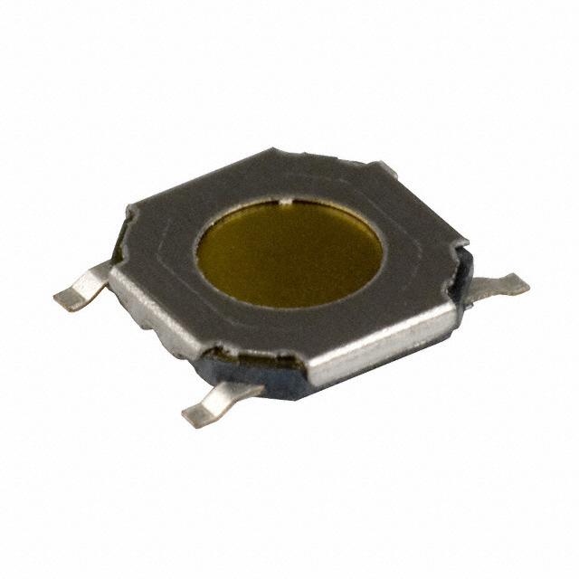
PTS 525 Series
Microminiature Tact Switch for SMT
Features/Benefits
• Ultra low profile, 0.8 & 1.5 mm
actuator height
• Long life
• Compact package of 5.25 x 5.25 mm
saves PCB space
Typical Applications
• Consumer products
• Instrumentation
• Computer products
• Hand-held devices
• RoHS compliant and compatible
B
Environmental
FUNCTION: Momentary action
CONTACT ARRANGEMENT: SPST, N.O.
TERMINALS: PC pins
OPERATING TEMPERATURE: -40˚C to 60˚C
Process
Mechanical
SMT capable of IR solder process. Lead free soldering
process compatible. Do not clean switch with ¡solvents.
ACTUATION FORCE: PTS525 models: 160 grams, 260 grams
LIFE EXPECTANCY: 100,000 operations.
Materials
BASE: 6/6 nylon or glass filled polyester (PBT) (UL 94V-0).
ACTUATOR: 6/6 nylon or polyacetal (UL 94HB).
DOME CONTACTS: Phosphor bronze, silver clad.
STATIONARY CONTACTS: Brass, silver plated.
TERMINALS: Brass, silver plated. Insert molded.
Electrical
CONTACT RATING: 50 mA @ 12 V DC.
DIELECTRIC STRENGTH: 250 V AC min.
CONTACT RESISTANCE: 100 mΩ max. initial.
INSULATION RESISTANCE: 1011 Ω min.
ELECTRICAL TRAVEL: 0,30 ± 0,15 mm
Packaging
3000 pieces per Tape and Reel
NOTE: Specifications listed above are for switches with standard options.
For information on specific and custom switches, consult Customer Service Center.
How To Order
Our easy build-a-switch concept allows you to mix and match options to create the switch you need. To order, select
desired option from each category and place it in the appropriate box.
P
T
S
5
2
5
S
S
M
T
R
L
F
S
Termination
S Surface mount
Actuation Force
M 160 grams
K 260 grams
Total Height
08 0,8 (.032) high
10 1,5 (.059) high
RoHS compliant and compatible
Lead free silver
Packaging
SMTR Surface mount
tape and reel
Dimensions are shown: mm (inches)
Specifications and dimensions subject to change
18 july 12
B–15
www.ck-components.com
Tactile Switches
Specification
�PTS 525 Series
Microminiature Tact Switch for SMT
CIRCUIT DIAGRAM
0,8 MM HIGH
0,8
(0,032)
SM08
6,4
(0,252)
3
4
PCB LAYOUT
4,8
(0,189)
5,2
(0,205)
2,7
(0,106)
2
4
0,5
(0,02)
1
3
8,0
(0,315)
4,8
(0,189)
3,7
(0,146)
5,2
(0,205)
4,4
(0,173)
1,5 MM HIGH
ø2
(ø 0,079)
CIRCUIT DIAGRAM
1
2
3
4
0,8
(0,032)
1,2
(0,047)
SM10
1,5
(0,059)
Tactile Switches
B
2
4,7
(0,185)
ø 3,0
(ø 0,118)
1
6,4
(0,252)
4
4,8
(0,189)
2,6
(0,102)
4,8
(0,189)
8
(0,315)
4,8
(0,189)
2
3
0,5
(0,02)
1
PCB LAYOUT
5,2
(0,205)
3,7
(0,146)
5,2
(0,205)
4,4
(0,173)
TAPE & REEL
SM08
SM10
6,6
(0,26)
0,3
(0,012)
ø 1,5
(ø 0,059)
2,1
(0,083)
8
(0,315)
2
(0,079)
4
(0,158)
12
(0,472)
4,0
(0,158)
12,0
(0,472)
5,5
(0,217)
2,0
(0,079)
5,5
(0,217)
8,0
(0,315)
ø 1,5
ø 0,059
7,2
(0,285)
2,1
(0,083)
5,5
(0,216)
DIRECTION OF FEED
DIRECTION OF FEED
Dimensions are shown: mm (inches)
Specifications and dimensions subject to change
18 july 12
B–16
www.ck-components.com
�